
 English
 русский
 Español
 عربى
عربى 中文简体
中文简体
Aktualności
Dom / Aktualności / Wiadomości branżowe / Wszystkie kable samonośne dielektryczne (ADSS): przewodnik po budowie, typach i specyfikacjach

Pojedyncze przęsło antenowe o długości 200 metrów. Żadnych przewodów komunikacyjnych, żadnych metalowych elementów, żadnej załogi wyłączającej linię energetyczną poniżej. To jest dokładnie scenariusz, w którym Wszystkie kable samonośne dielektryczne (ADSS). zasługuje na swoje miejsce — i dlaczego operatorzy mediów i wykonawcy telekomunikacyjni wdrażają go na dużą skalę do wdrażania napowietrznych włókien światłowodowych.
W tym przewodniku opisano budowę kabla ADSS, miejsca, w których działa najlepiej, które warianty pasują do konkretnych środowisk i co należy sprawdzić przed wybraniem kabla do następnego projektu.
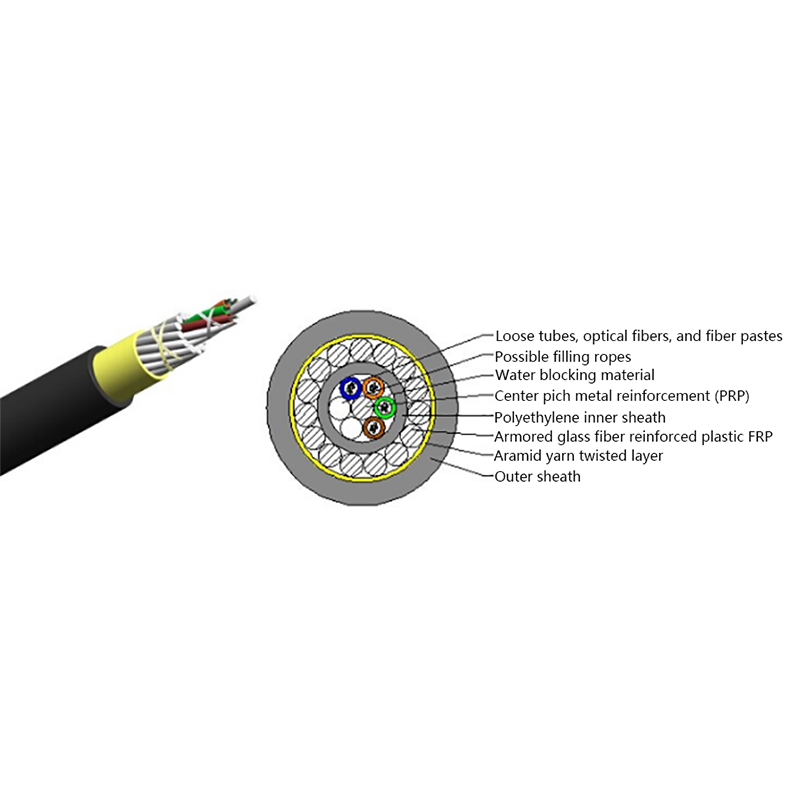
W przeciwieństwie do konwencjonalnego światłowodu, który wymaga oddzielnego stalowego przewodu komunikacyjnego do wsparcia, kabel ADSS został zaprojektowany tak, aby był całkowicie samonośny. Obciążenie konstrukcyjne przenoszone jest przez wysokomodułowa przędza aramidowa owinięty wokół rdzenia kabla — zapewniając mu wytrzymałość na rozciąganie bez stosowania ani jednego metalowego elementu w dowolnym miejscu konstrukcji.
Ta niemetalowa konstrukcja to nie tylko wybór zmniejszający wagę. Oznacza to, że kabel jest elektrycznie obojętny. Można go zainstalować na tej samej wieży, co linie przesyłowe wysokiego napięcia do 220 kV, bez ryzyka galwanicznego, a załogi mogą na nim pracować, podczas gdy linia energetyczna poniżej pozostaje pod napięciem, co stanowi znaczną zaletę w zakresie bezpieczeństwa i funkcjonalności w sieciach pod napięciem.
Rozpiętość waha się zazwyczaj od 50 metrów w przypadku krótkich miejskich tras dystrybucyjnych do 700 metrów lub więcej w przypadku długich wiejskich korytarzy przesyłowych. Pole przekroju poprzecznego aramidu jest dostosowywane projektowo w celu dopasowania do wymagań dotyczących zwisu i naprężenia dla każdej określonej długości przęsła.
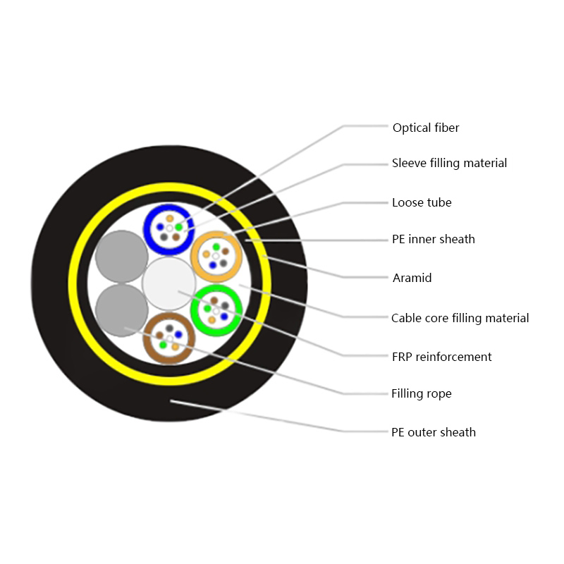
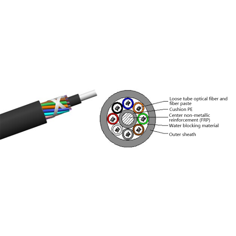
Zrozumienie struktury pomaga w dokładniejszej ocenie specyfikacji. Standard Całkowicie dielektryczny, samonośny kabel optyczny ADSS składa się w następujący sposób:
Rezultatem jest kabel, który jest lekki, kompaktowy i wydajny konstrukcyjnie – zmniejszając obciążenie wieży w porównaniu z cięższymi, opancerzonymi alternatywami.
Cztery cechy określają, czy kabel ADSS nadaje się do danego projektu:
Standardowy ADSS obsługuje większość wdrożeń mediów i telekomunikacji. Dwa szczególne warunki wymagają ulepszonych wariantów.
Trasy leśne i leśne narażać kable na gryzienie przez wiewiórki — awaria występująca częściej, niż wielu inżynierów się spodziewa. The kabel optyczny ADSS zapobiegający wiewiórce rozwiązuje ten problem poprzez zastosowanie warstwy ochronnej z tworzywa sztucznego wzmocnionego włóknem szklanym o wysokiej wytrzymałości, której gryzonie nie mogą przeniknąć. Zachowuje wszystkie standardowe właściwości ADSS – bezpieczeństwo odgromowe, strukturę dielektryczną, możliwość instalacji pod napięciem – jednocześnie dodając mechaniczną ochronę przed szkodami spowodowanymi przez dzikie zwierzęta. Ta sama konstrukcja zapewnia również odporność na dziobanie ptaków.
Mieszane korytarze zagrożone gryzoniami szerzej może wymagać niemetalowy kabel optyczny przeciw gryzoniom , który wykorzystuje podobne podejście ochronne bez wprowadzania żadnego materiału przewodzącego, zapewniając bezpieczeństwo kabla podczas wspólnego wdrażania wysokiego napięcia.
Kabel ADSS jest rutynowo wdrażany przez przedsiębiorstwa energetyczne, które dodają komunikację światłowodową do istniejącej napowietrznej infrastruktury przesyłowej, przez operatorów telekomunikacyjnych budujących sieci napowietrzne ostatniej mili wzdłuż pasów użytkowych oraz przez gminy tworzące odporne łącza szkieletowe między podstacjami lub zdalnymi punktami monitorowania. Instalacja jednoprzebiegowa — bez wstępnego mocowania posłańca i drugiej przepustki dla załogi — znacznie skraca czas pracy na długich trasach wiejskich.
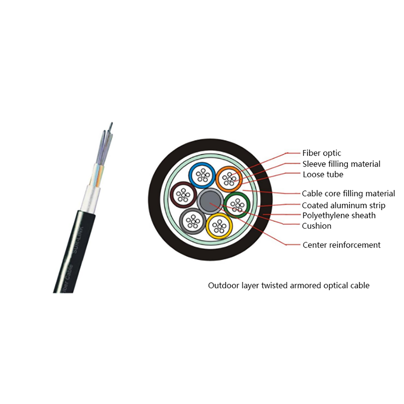
W przypadku projektów, w których trasa napowietrzna ostatecznie przechodzi pod ziemię, można podłączyć ADSS zewnętrzne wielowarstwowe kable optyczne w punktach przejściowych, umożliwiając stałą liczbę włókien w zróżnicowanym terenie bez konieczności przeprojektowywania konstrukcji włókna rdzeniowego.
Gdy światłowód musi także dotrzeć do budynków bezpośrednio z sieci napowietrznej, Kable motylkowe FTTH zapewnić końcowe połączenie od słupa do lokalu abonenta.
Trzy wejścia sterują prawidłową specyfikacją kabla. Zrób to dobrze, a reszta projektu będzie logiczna.
Wykresy liczby włókien, pojedynczego lub podwójnego płaszcza oraz wykresy ugięcia specyficznego dla rozpiętości są drugorzędne w stosunku do tych trzech danych wejściowych środowiskowych — pochodzą z analizy obciążenia, a nie z założeń.
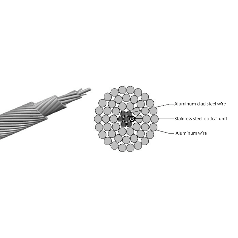
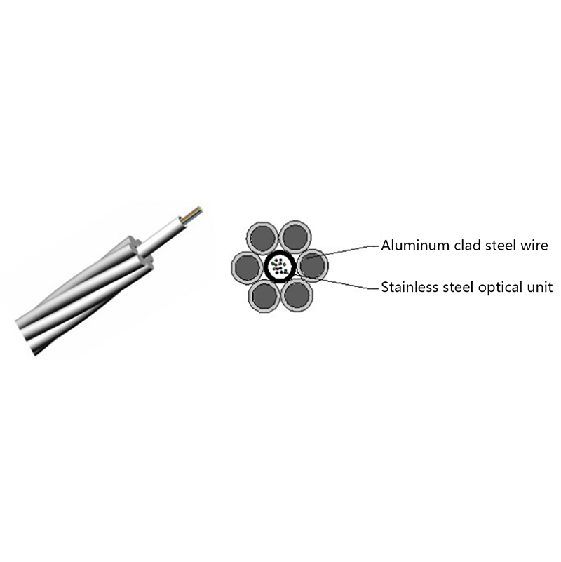
Typowym punktem decyzji jest to, czy użyć ADSS, czy OPGW (optyczny przewód uziemiający) na nowej lub zmodernizowanej linii przesyłowej. OPGW zastępuje istniejący napowietrzny przewód uziemiający i zapewnia uziemienie oraz światłowód w jednym przewodzie — właściwy wybór, gdy przewód uziemiający i tak wymaga wymiany. ADSS jest lepszą opcją, gdy istniejący przewód uziemiający nadaje się do użytku, gdy dodaje się światłowód do już zasilanej linii bez przerw lub gdy budżet instalacyjny nie uzasadnia całkowitej wymiany sprzętu. Te dwa rozwiązania raczej się uzupełniają niż konkurują.
Prośba o telefon dzisiaj